Install Guide

Pebble Install Guide

This guide walks you through physical installation, setup, testing, and final checks using simple installer-friendly language.

Choose a guide section

Section 1: Before You Begin

Know these setup details first

  • Which Pebble model you are installing: eco1, eco2, or Pebble Plus.
  • Whether the Monitoring Device has already been created in the portal.
  • Whether the physical device/site timezone has been selected in the portal.
  • Which Main Tank Sensor Type is being used: ultrasonic distance sensor or submersible level sensor.
  • Whether the site uses one Main Tank only, a Main Tank with Reserve Tank, or a larger RS485-based setup.
  • Whether Manual Level Input is being used as a trial/no-sensor setup for the Main Tank.
  • Whether the tank needs Tank Objects / Additional Measurements for internal shapes, side spaces, or connected capacity.
  • If Pebble Plus is being used, whether each RS485 device has already been commissioned to the intended shared bus standard and a unique address.

Simple meanings

Monitoring Device
The Monitoring Device is the portal record created in the dashboard. It stores the device serial, link code, site location, timezone, and tank relationship.
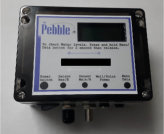
Pebble Unit
The Pebble Unit is the physical hardware installed on site.

Link Code
The Link Code connects the physical Pebble Unit to the correct Monitoring Device in the portal.

Main Tank
The Main Tank is the primary tank linked to the Monitoring Device. It is connected as Tank A / Sensor A / reading 1.

Reserve Tank
The Reserve Tank is an optional backup tank connected as Tank B / Sensor B / reading 2. It is added after the Main Tank is created and marked as having a reserve.

Portal
The Portal is the website dashboard where the Monitoring Device, Link Code, tank setup, timezone, and tank status are managed.

Main Tank Sensor Type
The portal setting that tells the system how to interpret the Main Tank reading. Ultrasonic means top-down distance reading. Submersible means in-water level/depth reading.
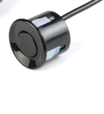
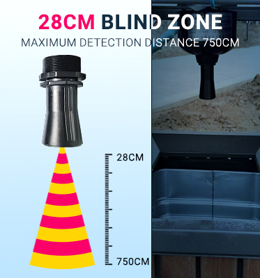
Ultrasonic sensor
An ultrasonic sensor sits above the water and measures distance down to the water surface.

Submersible sensor
A submersible sensor goes down into the tank and measures water pressure from inside the tank instead of reading from above. Some versions use 4-20mA, 0-5V, 0-10V, or RS485 / Modbus. For Pebble Plus, confirm you have the RS485 / Modbus version before wiring it to the RS485 bus.

Manual Level Input
Manual Level Input is a Main Tank only trial/no-sensor mode. It allows the customer to enter fluid levels manually before installing a physical sensor. Manual Level Input cannot be used with a Reserve Tank.

Tank Objects / Additional Measurements
Tank Objects are used when a tank has internal shapes, side spaces, wedges, blocks, or connected areas that change usable capacity.
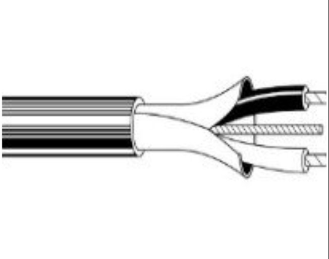
RS485 bus
The RS485 bus is the shared wired sensor line used on Pebble Plus. It lets the controller communicate with compatible sensors on the same wiring run. Each RS485 device must have a unique address and use the intended shared communication standard.

Section 2: Confirm The Portal Is Ready

2

Portal setup before going to the site

Before installing the physical Pebble Unit, create or select the Monitoring Device in the portal.

  1. Create or select the Monitoring Device.
  2. Choose the Complex and Building where the device will be installed.
  3. Select the physical device/site timezone. Reading times, tank-top events, and device time-sync behavior use this site timezone.
  4. Save the Monitoring Device so the portal can generate the Device Serial and Link Code.
  5. Use that Link Code on the Pebble setup page to link the physical Pebble Unit to the correct Monitoring Device.

Important: The Monitoring Device is the portal record. The Pebble Unit is the physical hardware. The Link Code connects them together.

Section 2B: Tank Setup In The Portal

2B

Use the device-first tank setup flow

After the Monitoring Device exists, use the Device page to link or create the Main Tank for that device.

  • If the Main Tank already exists and is not linked to another device, link it from the Device page.
  • If the Main Tank does not exist yet, create the Main Tank from the Device workflow.
  • The Main Tank should match the physical tank connected to Sensor A / reading 1.
  • Device linking should be managed from the Device page, not by manually changing the device inside the tank update form.

Main Tank Sensor Type

Ultrasonic distance sensor:
The sensor is mounted above the water and measures distance down to the water. High Water Overflow and Height of Sensor can be separate values.

Submersible level sensor:
The sensor reads from inside the water. High Water Overflow is treated as the full/usable water level, and Height of Sensor is automatically treated as the same value.

Manual Level Input

  • Manual Level Input is for Main Tank trial/no-sensor mode only.
  • Use it when the customer wants to start with manual fluid-level entry before installing a physical sensor.
  • Manual Level Input cannot be used with a Reserve Tank.
  • If Manual Level Input is enabled, Reserve Tank is turned off.
  • If Reserve Tank is enabled, Manual Level Input is turned off.

Reserve Tank Setup

  • Reserve Tanks are added after the Main Tank is already created.
  • On the Main Tank, “This tank has a reserve” must be enabled before adding the Reserve Tank.
  • Sensor A / reading 1 is the Main Tank.
  • Sensor B / reading 2 is the Reserve Tank.
  • Reserve Tank Sensor Type works like Main Tank Sensor Type: ultrasonic uses a separate Sensor Height, while submersible treats Sensor Height as equal to High Water Overflow.

Tank Objects / Additional Measurements

  • Use Tank Objects only when a tank has internal shapes, side spaces, wedges, blocks, or connected spaces that change usable capacity.
  • Enable “Has additional tank measurements” on the Main Tank before adding Main Tank Objects.
  • Enable “Has additional tank measurements” on the Reserve Tank before adding Reserve Tank Objects.
  • Main Tank Objects affect Tank A / Sensor A.
  • Reserve Tank Objects affect Tank B / Sensor B.
  • Use ADD for extra connected space that holds fluid. Use SUBTRACT for solid objects or shapes that reduce usable capacity.

Installer note: The portal tank setup and the physical Pebble Sensor Setup must agree. For example, if the portal Main Tank Sensor Type is Submersible, the device Sensor Setup should use the matching submersible/RS485/analog configuration for that installation.

Section 3: Open Installer Mode

3

Open Link Device

Press and release the Pebble menu button. Do not hold the button. This opens the temporary Pebble setup Wi-Fi so the installer can access the local setup menu.

Connect to the Pebble setup Wi-Fi, then open http://192.168.4.1. Log in using the setup access code. setup1234

Installer Mode: During setup, Pebble can keep its setup Wi-Fi open for the installer while also connecting to the site Wi-Fi in the background. This lets the installer stay on the local setup page while Pebble communicates with the backend.

Section 4: What You Will See On Screen

1. Login / Home

The installer logs in and starts with Link Device, Connection Setup, or Sensor Setup.

2. Link Device

This page is used to enter the Link Code and connect the Pebble Unit to the correct Monitoring Device.

3. Connection Setup

This page is used for Wi-Fi settings, mobile APN details, update timing, and communication preferences.

4. Sensor Setup

This page is used to choose the sensor type, test each reading, and confirm any tank-top switch.

Section 5A: Wi-Fi Connection Setup

Now it's time to put the device online

Pebble connects to the site network through its temporary setup Wi-Fi. During this step, your phone or laptop connects directly to Pebble, opens the Wi-Fi setup page, and saves the normal site Wi-Fi details into the device.

Important: The Pebble setup Wi-Fi is only for configuration. It may say “No Internet” on your phone. That is normal. Stay connected until the Wi-Fi setup is saved.

Quick setup details

Setup Network
Pebble-xxxxxx
Setup Password
setup1234
Setup Address
http://192.168.4.1
Auto Redirect
Usually within a few seconds

Before you begin

  • Have the site Wi-Fi name and password ready.
  • Stand close enough to Pebble to see the setup Wi-Fi network.
  • Use a 2.4 GHz Wi-Fi network if the site router separates 2.4 GHz and 5 GHz networks.
  • Complete Link Device first if this Pebble has not yet been linked to a Monitoring Device.

Wi-Fi setup steps

  1. 1
    Open your phone or laptop Wi-Fi settings.

    Look for the temporary Pebble setup network.

  2. 2
    Connect to Pebble-xxxxxx

    Use password setup1234.

  3. 3
    Stay connected if your device says there is no internet.

    This message is normal because you are connected directly to Pebble for setup, not to the internet.

  4. 4
    Open the Pebble Wi-Fi setup page.

    If it does not open automatically, open http://192.168.4.1 in your browser.

  5. 5
    Select the site Wi-Fi and save.

    Choose the normal site Wi-Fi network, enter the password, and save. Pebble will immediately try to join that network.

If the Wi-Fi connection works

Pebble will join the site Wi-Fi while keeping the Pebble setup Wi-Fi open for the installer. Your phone or tablet can stay connected to http://192.168.4.1 while Pebble communicates with the backend. The setup Wi-Fi closes only when Finish Setup is pressed.

If the Wi-Fi connection fails

Pebble will return to setup mode. Reconnect to the Pebble setup Wi-Fi, reopen the setup address, check the site Wi-Fi name and password, and try again.

Troubleshooting tips

  • If the setup page does not open, confirm you are connected to the Pebble setup Wi-Fi and manually open http://192.168.4.1.
  • If your phone switches back to mobile data or another Wi-Fi network, reconnect to Pebble-xxxxxx and try again.
  • If the site Wi-Fi is weak near the controller, move the controller or improve the site Wi-Fi signal before leaving the installation.
  • If the device screen shows a Wi-Fi error, recheck the site Wi-Fi password and confirm the selected network is available.

Section 5B: Connection Setup For Mobile Units

Only for units with mobile service

Some Pebble units include a mobile communication module. These units can send updates through the mobile network instead of relying only on site Wi-Fi.

  • Make sure the SIM card is installed and active.
  • In Connection Setup, enter the mobile APN details if required.
  • Use the communication setting that matches the install.
  • Run the mobile connection test before leaving the site.

Tip: If the site Wi-Fi is weak or unreliable, a mobile unit may still continue sending updates through the mobile network when set up correctly.

Section 6: Link Device Or Link All Slots

Choose the correct linking method

Link Device

Use Link Device when linking one physical Pebble slot to one Monitoring Device.

Link All Slots

Use Link All Slots on Pebble Plus when one physical Pebble Plus unit is being linked to up to three Monitoring Devices. Each slot uses its own Link Code from the portal.

Important: Link All Slots requires Pebble to be connected to the site Wi-Fi while the setup Wi-Fi remains open. If the Link All Slots page says internet is required, return to Wi-Fi Connection Setup first.

Section 7: Moving Or Re-Linking A Physical Pebble

If the same physical Pebble is being moved to another Monitoring Device or another account, release the hardware in the portal first, then use Clear Cloud Link on the Pebble local setup page.

  1. In the portal, open the old Monitoring Device and choose Release Hardware.
  2. On the physical Pebble, open Clear Cloud Link.
  3. Generate fresh Link Codes for the new Monitoring Device or devices.
  4. Use Link Device or Link All Slots to bind the physical Pebble again.

Do not confuse this with replacement: Start Replacement is only for replacing the physical board while keeping the same logical Monitoring Device and tank history.

Section 8: Sensor Setup

8

Open Sensor Setup

Sensor Setup is where you tell the physical Pebble Unit what type of sensor is connected and where you prepare the live reading test.

  • Choose the matching quick setup if one applies.
  • Confirm the sensor type for each reading.
  • Confirm that the physical sensor setup matches the portal Tank Sensor Type.
  • For ultrasonic sensors, confirm the sensor is mounted above the water and aimed straight down.
  • For submersible sensors, confirm the correct electrical/RS485 version was selected and wired correctly.
  • If used, confirm how the tank-top switch is connected.

Portal check: Before final testing, confirm the Monitoring Device is linked to the correct Main Tank, the Main Tank Sensor Type is correct, and any Reserve Tank or Tank Objects are already configured in the portal.

8A

RS485 commissioning and service tools

Use these tools when an RS485 device needs to be commissioned or corrected before the live bus is finalized. This is most common when a device arrives with the wrong address, the wrong communication speed, or another setting that must be corrected before normal operation.

  • Sensor Number Tools: Use this to read, assign, and scan sensor numbers for RS485 ultrasonic and RS485 submersible sensors.
  • Analog Sensor Number Tools: Use this to read, assign, and scan addresses for RS485 analog input modules.
  • Switch Box Service: Use this only if the tank-top switch box needs service or address recovery. In normal installs, the switch box address is usually pre-configured.
  • RS485 Ultrasonic Service: Use this for ultrasonic address recovery, communication-speed recovery, force-9600 actions, and diagnostics.
  • Submersible Sensor Service: Use this for submersible sensor address work, communication-speed changes, zero-offset correction, save actions, and related diagnostics.

Important: Some per-reading service buttons only appear after you save the reading with the correct sensor type and reload the page. This is normal.

Commissioning rule: Finish address and communication-speed corrections before placing the full RS485 bus into normal operation. On the final live bus, every device should have a unique address and the intended shared communication standard.

If the installation uses Pebble Plus and any RS485 device is not responding correctly, open the RS485 Wiring Guide and confirm topology, termination, polarity, grounding, and branch length before assuming the device is faulty.

8B

Test the reading

Important: If you are assigning addresses on the RS485 bus, connect only one sensor at a time while doing that step.

  • Check reading now: Use the test button to confirm a live reading appears.
  • Main and Reserve: If using eco2, test both the main and reserve readings.
  • Tank-top switch: If the setup uses a tank-top switch, test that the status changes when the switch is triggered.
  • RS485 commissioning: If an RS485 device needs a corrected address or bus speed, use the matching service page before final testing.
  • Submersible offset: If a submersible sensor communicates correctly but reads consistently off, review and correct the offset value in the Submersible Sensor Service page.
  • Existing analog sensor: For analog installs, use the current electrical value tools to confirm the live signal and help set the empty and full calibration points.
8C

Save Setting

After all readings and service actions are confirmed, save the settings. When the device returns to normal operations it will continue sending updates based on the setup you entered.

On Pebble Plus, all commissioned RS485 devices on the live bus should now have unique addresses and be using the intended shared bus standard.

Section 9: Reporting / Update Settings

9

Open Connection Setup

After the Link and Sensor Setup are complete, open Connection Setup.

  • Send an update when the level changes by?: Aside from the normal update time, you can set the device to update on level change.
  • Last Check-in time for the day: You can change the device last check-in update. Default is 24-hr clock time of 2350 hrs.
  • Send Updates every (hours) : Choose how often the device should send updates.

Before you leave the job site. Confirm the website has been updated with an expected values and date time..

Section 10: Final Checks Before Leaving

  • Confirm the portal Monitoring Device is linked to the correct Main Tank.
  • Confirm the device/site timezone is correct in the portal.
  • Confirm the portal Main Tank Sensor Type matches the physical sensor setup.
  • If a Reserve Tank is used, confirm the Main Tank is marked as having a reserve and the Reserve Tank setup is complete.
  • If Tank Objects / Additional Measurements are used, confirm the correct Main Tank Objects or Reserve Tank Objects are configured.
  • Make sure the device powers on normally.
  • Make sure the correct tank or tanks show a reading.
  • Make sure the correct sensor type was selected.
  • Make sure the reading changes when the water level changes or when the sensor is checked.
  • If a tank-top switch is used, make sure its status changes when tested.
  • On Pebble Plus, make sure each RS485 device on the live bus has a unique address.
  • On Pebble Plus, make sure all commissioned RS485 devices are using the intended shared bus standard before leaving the site.
  • If a service page was used, confirm the corrected address, bus speed, or submersible offset before final save.
  • Make sure all settings were saved before you leave the site.

Finish Setup

Finish Setup is the final installer close-out step. It closes the temporary Pebble setup Wi-Fi and returns the device to normal runtime mode.

  • Use Finish Setup only after Wi-Fi, linking, sensor setup, and final checks are complete.
  • After pressing Finish Setup, the browser will show a confirmation page.
  • A few seconds later, Pebble-xxxxxx will disappear and your phone or tablet will disconnect from the setup Wi-Fi.
  • The device continues normal operation using the saved site Wi-Fi or configured backhaul method.

Finish Setup does not:

  • Generate Link Codes.
  • Claim slots.
  • Erase Wi-Fi credentials.
  • Release hardware.
  • Clear the cloud link.

Section 11: Device Status & Troubleshooting

11

What the device screen and LED are telling you

Pebble uses the LCD screen and the LED blink pattern together to show status and the next action to take. Use this guide to match the device message with the correct next step.

Important: On current firmware, the normal ready state is "READY" on line 1 and "Standby" on line 2. During Wi-Fi setup, you may see either "SETUP / 192.168.4.1" or "SETUP / WiFi cfg" depending on which setup step the device is in.

Screen Line 2 LED Pattern Meaning Installer action
SETUP 192.168.4.1 Slow blink Device is in setup AP mode. Connect to the setup Wi-Fi and open the setup page.
SETUP WiFi cfg Slow blink Device is in Wi-Fi configuration mode. Finish Wi-Fi setup and save the site network details.
WIFI Connecting Medium blink Connecting to Wi-Fi. Wait. If it does not connect, check the Wi-Fi details and signal strength.
WIFI ERR Check WiFi Slow blink Wi-Fi connection failed. Re-enter Wi-Fi details and try again.
UNBOUND Claim dev Slow blink Device is not linked to a Monitoring Device. Open Link Device and enter the Link Code from the portal.
CLAIM Claiming Medium blink Link request is in progress. Wait for completion.
CLAIMOK Bound Solid ON Device link completed successfully. No action needed unless you are linking another slot on Pebble Plus.
CODEERR Regen web Double blink Link Code expired or is no longer valid. Generate a new Link Code in the portal and try again.
CLAIMER Try again Double blink Link failed. Retry and confirm the Link Code and selected slot are correct.
CLOUD Retry Double blink + pause Cloud service could not be reached. Check internet access, DNS, and firewall / HTTPS access.
API ERR Retry Triple blink + pause Server returned a non-success response. Retry first, then review backend logs if needed.
BADRESP Retry Triple blink + pause Unexpected or invalid server response. Retry, then verify firmware and backend response format.
RESOLVE Retry Double blink + pause Resolve step failed after network connection. Retry after confirming Wi-Fi and cloud connectivity.
SENSERR Check sens Fast blink Sensor problem detected. Check wiring, sensor type, address settings, and power.
TIMEOUT Retry Fast blink Sensor did not respond in time. Inspect cabling and communication wiring.
READY Standby Solid ON Device is in the normal ready state. No action needed.

LED pattern guide

Patterns
  • Slow blink = about an 0.8 second interval
  • Medium blink = about a 0.35 second interval
  • Fast blink = about a 0.12 second interval
  • Solid ON = normal ready state
Grouped patterns
  • Double blink = grouped pair of flashes
  • Triple blink + pause = grouped triple flashes followed by a pause
  • Heartbeat = short ON, long OFF during update / OTA activity
  • Repeating burst = very fast repeated flashes during factory reset
If the reading is missing or wrong, first check power, wiring, model selection, Link status, sensor type, and saved address or calibration values. Then test the sensor again from the setup page. If an RS485 device still does not respond, use the matching service page to check address, bus speed, and diagnostics.

Hardware Installation

This section covers physical mounting, cable routing, and power. Setup and testing are covered in the Setup & Testing tab.

Choose your model

eco1 uses 1 ultrasonic sensor, eco2 uses 2 ultrasonic sensors for Main Tank and Reserve Tank, and Pebble Plus uses compatible RS485 ultrasonic and submersible sensors on the shared RS485 bus.
Pebble eco1
1 Tank
One ultrasonic sensor
Controller
Sensor included
1 Sensor
JSN
Pebble eco2
Main + Reserve
Controller
Sensors included
2 Sensors
Main Reserve
Pebble Plus uses the RS485 bus. That means the sensors share a wired communication line instead of each wiring directly to the controller.
Pebble Plus
RS485 Bus
RS485
Sensor type (Plus only)
Choose the sensor hardware used on the RS485 bus.

Hardware Installation Steps

These steps cover tank mounting, cable routing, and power. Setup and testing are covered in the Setup & Testing tab.
Safety & expectations
  • Install time varies by tank, access, and cable routing.
  • Correct aiming and stable mounting are important for reliable readings.
  • If you are not comfortable working inside or around a tank, use a qualified installer.
  • Use safe access methods, proper tools, and weather-sealed connections.

Tools & materials
  • Drill and suitable bits
  • Screwdriver and mounting hardware
  • Sealant for wall penetrations
  • Cable protection and strain relief as needed
Before mounting

Plan the cable route first. Choose a controller location with good Wi-Fi signal and a clean route back to the tank.

Strain relief Sensor cable

Mounting rules
  • Aim the ultrasonic sensor straight down toward the water surface.
  • Avoid obstructions that could block or reflect the reading.
  • Mount the sensor securely so it does not shift after installation.
  • Keep weather-exposed joins sealed and strain-relieved.
eco2 note: Connect the main sensor to Sensor A / reading 1 and the reserve sensor to Sensor B / reading 2 so the portal setup matches the physical installation.
Cable routing
Cable runs
Protect connectors while routing and avoid sharp strain on the cable.

Controller mounting
  • Mount the controller where Wi-Fi signal is reliable.
  • Keep it close enough to the tank to avoid unnecessary cable runs.
  • Seal any cable entry holes after the cable is routed.
Cable pulling tip

Use a pull-string or fish tape when routing cable through a wall or conduit. Smooth and protect the connector during the pull.

Solar
Solar kit
Wall outlet / adapter
Power adapter
After the hardware is installed, switch back to the Setup & Testing tab to connect Wi-Fi, test the readings, and finish setup.

Pebble Connection Overview

eco1 / eco2 direct ultrasonic sensors • Pebble Plus RS485 bus • power • wiring

eco1 / eco2 — Direct Ultrasonic Sensor Setup

eco1 = 1 sensor • eco2 = main + reserve
Pebble eco unit
Pebble controller
JSN sensor
Ultrasonic sensor
Tank top connection
Tank top connection
Placement hint
Mount above the water and aim down
Pebble eco device
Controller
Ultrasonic sensor
Direct wiring
Tank level reading
Main only, or main + reserve

Pebble Plus — RS485 Bus Setup

Use a true daisy-chain bus and avoid star wiring.
Pebble Plus controller
IP68 junction
IP68 junction
Wiring
Bus wiring connections
Pebble Plus
RS485 trunk cable
Sensor 1
On the RS485 bus
Sensor N
Continue the daisy-chain
Typical Plus sensor choices
  • Ultrasonic sensor on the RS485 bus
  • Another compatible ultrasonic sensor on the RS485 bus
  • Compatible submersible sensor on the RS485 bus
  • Apply RS485 termination only at the end of the bus

Wiring Reference

Use the matching wiring method for your selected model.
Sensor side
Signal  → Sensor signal
Ground  → Sensor ground
Controller side
Signal  → Pebble sensor input
Ground  → Pebble ground
eco models use direct ultrasonic sensor wiring. Keep joins sealed and protected.
RS485 bus pairing (recommended)
Plus only
  • Pair 1: RS485 A / B
  • Pair 2: Power + / Ground
  • Shield: Bond at one end only if shielded cable is used
Use a true daisy-chain line, not star wiring. Terminate only at the final device on the bus.

Power Options

12V DC adapter or suitable 12V solar setup
Solar
Solar example
Adapter
12V adapter example
Use stable 12V DC power and protect exposed power connections from weather.
Use this as the high-level map. The exact hardware details depend on the model you selected.